Type 3.2 font editor
Make a Variable Font - Part I
By Allan Murray | Posted November 23, 2019
Variable fonts are the latest 'new' thing in typography - which is actually an 'old' thing - it's basically exactly Apple's TrueType GX variations technology from the 90's (which never really caught on). What is new is the collaborative effort between Microsoft, Google, Apple and Adobe to revive and update this technology and add it to OpenType specification. Due to these collarative efforts, most browsers now support variable fonts, as does Adobe Illustrator, Adobe Photoshop and very recently the latest version of Adobe InDesign - so things should fare better this time around.
Type 3.2 font editor (including freeware Type light) now support the creation of variable fonts. This tutorial will guide you through the process, and describes a recommended workflow - which should be followed in the order described.
If you are not familiar with the basic concepts of variable fonts, please read one of the references listed below.1 2
Step 1. Decide on the axis/axes to use
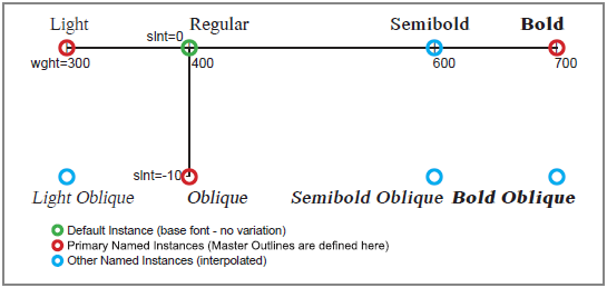
A variable fonts design space (a multidimensional space - don't hurt your brain) is made up of one or more variation axes, which represent the fonts variable attributes. Decide on what axes you are going to use for your font, then define and a maximum, a minimum and a default value for each one. Note that it is OK for an axis to extend in one direction only, in which case either default=minimum or default=maximum (as per slant axis below).
In this example our font will have two axes: slant and weight.
slant: minimum=-10 (Oblique), default=maximum=0 (Regular)
weight: minimum=300 (Light), default=400 (Regular), maximum=700 (Bold)
These are defined as recommended in the Variation Axis Tag Registry.3
This two dimensional design space is easily enough to visualise:
Step 2. Create/obtain a finished font for the default instance
You will first need a complete, finished, non-variable font to represent the default instance of your variable font (an instance is simply a location on the axes). In this example it will be a regular weight (weight=400), upright (slant=0) font. Use a finished font, as editing the glyphs of the default instance at a later stage will have secondary effects on the variable instances.
Step 3. Add the axis/axes
Select variable font mode from the view menu to open the variable font window.
From its drop-down arrow menu select axis list.
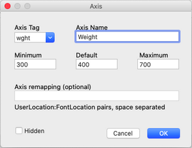
Click add
Select wght as axis tag:
Enter 300, 400, 700
(min, default and max)
Click ok
Click add
Select slnt as axis tag:
Enter -10, 0, 0
(min, default and max)
Click ok
Note that additional axes can easily be added later.
Step 4. Add named instances at the extremes of all axis/axes
Next we will create named instances at certain primary locations (a named instance is a location on the axes which has been given a name). These primary instances will be defined as instances that have one axis only at its maximum or minumum value, with all other axes at their default value.* In step 5 we will also define glyph outlines (primary master outlines) at these positions.
In our example there are three primary instances at:
slant=0(default), weight=300
slant=0(default), weight=700
slant=-10, weight=400(default)
*There are also instances at locations where more than one axis is at a maximum or minimum (slant=-10, weight=300) and (slant=-10, weight=700), but these are not primary instances, so we do not need to define glyph outlines there - they will be interpolated (interpolated here means magically mixing the glyphs of primary master outlines in specific proportions to get a 'morphed' glyph). These interpolated outlines may need tweaking, so we can define secondary master outlines here if required, but at a later stage (see Part II).
From the drop-down arrow menu select named instances.
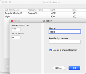
Click add
Enter 700 and 0 in the
wght and slnt boxes
Enter Bold in the name box
Tick use as shared location*
Click ok
Enter these named instances in the same way:
300 0 Light
400 -10 Oblique
*This saves the axis location with a name so that it can be easily referenced later when defining master outlines.
Step 5. Define primary master outlines
We will define the shapes of glyphs at the primary instances defined in the last step.
A master outline is a glyph explicitly defined at any position on the axes other than the default position. Master outlines are stored as offsets from the default outline, so altering the default outline beyond this stage will also alter the master outlines.
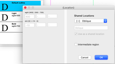
Select a glyph into the edit window, and press the add button on the variable font window.
Select the shared location for Oblique and press ok.
A copy of the default glyph will be listed in the variable font window. Do the same for the Bold and Light instances
You can select the master outlines and edit them in the edit window. Variable fonts require that the same number of points and contours be maintained between default and master outlines, so edit functions are restricted. This is indicated by the edit restricted button on the far right of the toolbar. Pressing this button will relax this restriction to some degree, allowing adding/deleting of points to the default glyph only (corresponding points will be added/deleted to the master outlines).
In this example, the Oblique master outline was created by applying a 10 degree
x-skew with the skew tool (select the skew tool, then right click on the edit window, and enter values shown below).
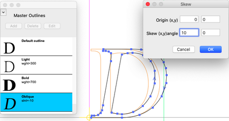
The Bold and Light master outlines were created by applying (x=-200, y=-20) and (x=40, y=20) strokes with the stroke tool. The clear master to default function on the glyph menu can also be used to restore a master outline to the default outline.
An action script can also be used to create and transform master outlines instead of doing each glyph manually (see Part II).
Step 6. Add additional named instances
Any number of additional named instances can be defined. These can also have master outlines defined for them (see Part II - Secondary and intermediate master outlines), but often will allowed to be interpolated. Named instances will appear as selectible options in the font-selector of the end-users application.
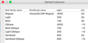
We will define these additional (interpolated) named instances:
700 -10 Bold Oblique
300 -10 Light Oblique
600 0 Semibold
600 -10 Semibold Oblique
Enter them as per Step 4, but do not tick use as shared location.
Step 7. Output the font
Once master outlines have been created for all glyphs, the font needs to be saved as a TrueType (.ttf) font. Type 3.2 does not currently support PostScript variable fonts (PostScript variable fonts are not widely supported yet).
These are the basic steps involved in creating a variable font using Type 3.2 and Type light font editors.
Please read Part II to learn about: action scripts, previewing, testing and use, adding secondary/intermediate master outlines, axis remapping and extracting single instances from a variable font.
References:
1. https://medium.com/variable-fonts/https-medium-com-tiro-introducing-opentype-variable-fonts-12ba6cd2369
2. https://www.monotype.com/resources/articles/variable-fonts-making-the-promise-a-reality
3. https://docs.microsoft.com/en-us/typography/opentype/spec/dvaraxisreg
To post a comment email: allanmurray@cr8software.net